
-
Highlight
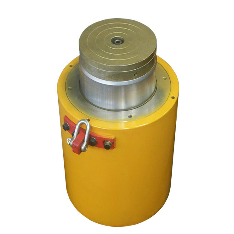
63Mpa Hydraulic Cylinder Jack
,Lock Nut Hydraulic Bridge Jack
,100T Hydraulic Cylinder Jack
-
Tonnage10-100T
-
Weight4.1-22.7kg
-
Work Pressure63Mpa
-
Extension126-198mm
-
StructurePiston Cylinder
-
Warranty1 Year
-
BrandZHONGTUO
-
Maximum Stroke57mm
-
Place of OriginChina
-
Brand NameZHONGTUO
-
CertificationCE; ISO
-
Minimum Order Quantity1PC
-
Packaging DetailsWooden Case
-
Delivery Time7-15Days
-
Payment TermsL/C, D/A, D/P, T/T, Western Union, MoneyGram
63Mpa Lock Nut Hydraulic Cylinder Jack One For Four
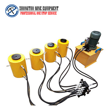
Description of Lock Nut Hydraulic Cylinder Jack
It is designed with a safety pressure maintaining device and a built-in pressure relief valve to prevent overload, so as to protect the jack for safe operation. And design four sets of stop valves, which can control the synchronous lifting and lowering of the jack at any time.
The connection of the device is connected by a high-pressure rubber hose and threaded joints, which are quick to use and overcomes the fast tradition. The shortcoming of joint oil leakage is mainly used in electric power, construction, machinery manufacturing, mining, railway bridges, shipbuilding, and other industries for equipment installation, jacking, and dismantling operations.
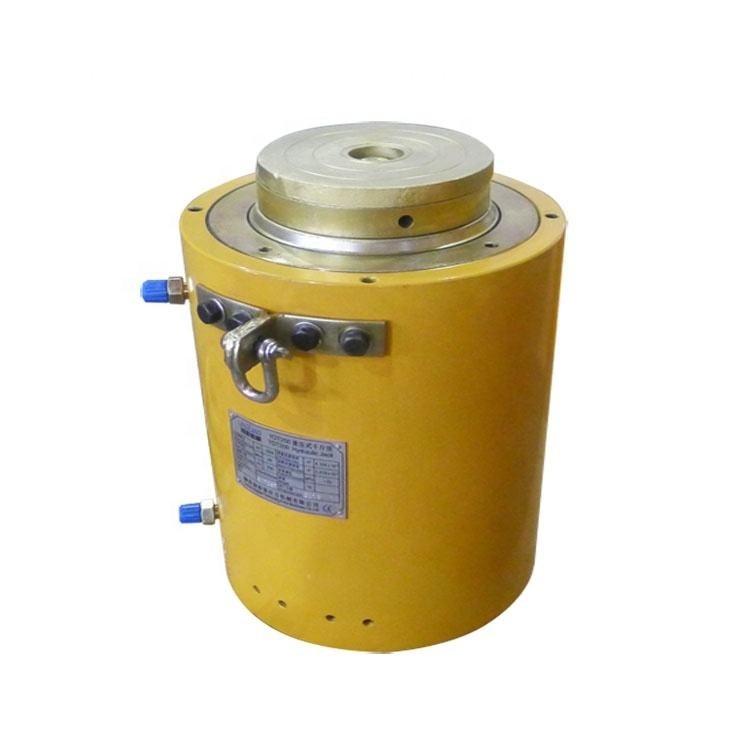
Technical Parameter of Lock Nut Hydraulic Cylinder Jack
| Model | Tonnage Ton |
Piston Stroke mm |
Height mm |
Extension mm |
Cylinder outer diameter D(mm) |
Weight Kg |
Work pressure Mpa(bar) |
| RM-TRCS-101×4 | 10 | 38 | 88 | 126 | 70 | 4.1 | 63 (630) |
| RM-TRCS -201×4 | 20 | 45 | 98 | 142 | 88 | 5 | 63 (630) |
| RM-TRCS -302×4 | 30 | 62 | 117 | 179 | 104 | 6.8 | 63 (630) |
| RM-TRCS -502×4 | 50 | 60 | 122 | 182 | 138 | 10.9 | 63 (630) |
| RM-TRCS -1002×4 | 100 | 57 | 141 | 198 | 188 | 22.7 |
63 (630) |
![]()
![]()
Features of Lock Nut Hydraulic Cylinder Jack
The jacking method can avoid high-altitude operations and is convenient for construction, but the jacking technology requires high requirements. A construction method in which the roof structure is assembled or poured on the ground and is gradually lifted to the design level by using jacks and alternately filled columns. This method does not require large-scale lifting equipment, and the entire roof that has been constructed on the ground, including roof waterproofing, paint, and pipelines, can be lifted into place at one time. The lightweight and compact design is suitable for narrow working spaces, and the piston automatically returns oil to the chrome-plated surface of the piston to prolong its life of the piston.
There are two kinds of Lock Nut Hydraulic Cylinder Jack
① The lifting method jack is supported upside down on the pad under the fulcrum of the roof structure, and the pad is the future column cap. In the beginning, the column cap is supported on both sides of the column base block. With the oil inlet and return of the jack, the temporary pad is filled in and the formal column block is replaced, and the column cap will gradually raise the roof structure. The column block is square and door-shaped (see the figure [schematic diagram of the lifting process of the upper jacking method and the column block diagram]). During the installation of the column block, it is advisable to lay cement mortar and welded sidebars in time, and seal the opening of the column block to enhance the stability of the column. In the upward jacking method, the lifting weight of the jack is constant and the stability is better, so it is widely used at present. Since it is a high-altitude operation, measures should be taken during the jacking process to prevent the roof structure from shifting, and attention should be paid to the synchronization of jacking.
② Lower jacking method. The jack is always placed on the column base, and the column blocks are filled with the top, which can reduce high-altitude operations, but the jacking weight gradually increases, especially when the movable fulcrum is formed at the column base, the stability is poor, and it has been seldom used.
Our products are sold all over the world, you can rest assured.