Post Tension Anchor With Multi Hole Anchorage For 12.7 / 15.2 / 17.8mm Steel Wire Cable
-
Highlight
Steel Wire Cable Post Tension Anchor
,Multi Hole Post Tension Anchor
,17.8mm Anchor Accessories
-
AutomationSemi-automatic
-
PC Strand1-15holes
-
Product ShapeRound
-
Wedge Form2 Chip Or 3 Chips
-
ApplicationBridge
-
MaterialAlloy Steel
-
Place of OriginCN
-
Brand NameZT
-
CertificationCE; ISO
-
Pricenegotiable
-
Delivery Time1 week
-
Payment TermsL/C, D/A, D/P, T/T, Western Union, MoneyGram
Post Tension Anchor With Multi Hole Anchorage For 12.7 / 15.2 / 17.8mm Steel Wire Cable
Anchorage is a permanent anchoring device used in prestressed concrete that is essential for applying the shrinkage force generated by prestressed tendons to the structure. The anchoring tool in post-tensioned structures or components can improve the bridge's bearing capacity, lengthen its span, and lower its weight by maintaining the tension of the prestressed tendons and transmitting it to the inside of the concrete.
![]()
Bridge support replacement, bridge and building reinforcement, steel reinforcement engineering, prestressed beam site construction, stay cable, suspension cable, urban interchange, light rail, high-rise building, water conservancy and hydropower dam, port pier, rock slope protection anchoring, tunnel mine roof anchoring, tower building, heavy lifting, etc.
![]()
| Technical data of YJM13 Anchorage | ||||||||||
| Specification | Anchor Head | Bearing Plate | Duct | Spiral Reinforcement | Stressing Jack | |||||
| ΦA | B | Square | Round | ΦE(ID) | ΦF | H | ΦG | N | ||
| C*D | ΦC*D | |||||||||
| YJM13-1 | 38 | 40 | 80×10 | - | 35 | 80 | 30 | 6 | 3 | QYC270 |
| YJM13-2 | 76 | 42 | 115×80 | 120×80 | 45 | 120 | 40 | 8 | 3 | YDC1100 |
| YJM13-3 | 83 | 42 | 120×80 | 130×80 | 50 | 120 | 40 | 10 | 3 | YDC1100 |
| YJM13-4 | 87 | 42 | 130×87 | 135×85 | 50 | 135 | 50 | 10 | 3 | YDC1100 |
| YJM13-5 | 97 | 42 | 140×92 | 140×100 | 55 | 140 | 50 | 10 | 4 | YDC1100 |
| YJM13-6 | 107 | 45 | 150×97 | 150×125 | 60 | 160 | 50 | 12 | 4 | YDC1100 |
| YJM13-7 | 107 | 45 | 150×97 | 150×125 | 60 | 160 | 50 | 12 | 4 | YDC1100 |
| YJM13-8 | 117 | 45 | 165×115 | 165×135 | 60 | 170 | 50 | 12 | 4 | YDC1500 |
| YJM13-9 | 127 | 48 | 175×125 | 175×140 | 70 | 180 | 50 | 12 | 4 | YDC1500 |
| YJM13-10 | 136 | 48 | 180×130 | 180×150 | 80 | 200 | 50 | 14 | 4 | YDC2500 |
| YJM13-11 | 138 | 50 | 180×130 | 180×150 | 80 | 200 | 50 | 14 | 4 | YDC2500 |
| YJM13-12 | 143 | 50 | 190×140 | 190×150 | 80 | 210 | 50 | 14 | 5 | YDC2500 |
| YJM13-13 | 147 | 53 | 190×140 | 190×150 | 80 | 210 | 50 | 14 | 5 | YDC2500 |
| YJM13-14 | 153 | 53 | 195×150 | 200×160 | 80 | 220 | 50 | 14 | 5 | YDC2500 |
| YJM13-15 | 157 | 55 | 195×150 | 200×160 | 90 | 220 | 50 | 14 | 5 | YDC2500 |
| YJM13-16 | 167 | 55 | 210×160 | 210×185 | 90 | 240 | 60 | 16 | 6 | YDC2500 |
| YJM13-17 | 172 | 58 | 220×175 | 235×185 | 90 | 240 | 60 | 16 | 6 | YDC3500 |
| YJM13-18 | 176 | 58 | 235×175 | 235×185 | 90 | 260 | 60 | 16 | 6 | YDC3500 |
| YJM13-19 | 176 | 58 | 235×175 | 235×185 | 90 | 260 | 60 | 16 | 6 | YDC3500 |
| YJM13-20 | 196 | 60 | 270×185 | 260×200 | 90 | 270 | 60 | 16 | 6 | YDC3500 |
| YJM13-21 | 196 | 63 | 270×185 | 260×200 | 90 | 270 | 60 | 16 | 6 | YDC3500 |
| YJM13-22 | 196 | 65 | 270×185 | 260×200 | 90 | 270 | 60 | 18 | 6 | YDC3500 |
| YJM13-23 | 206 | 65 | 295×245 | 275×260 | 100 | 280 | 60 | 18 | 6 | YDC4000 |
| YJM13-24 | 206 | 68 | 295×245 | 275×260 | 100 | 280 | 60 | 18 | 6 | YDC4000 |
| YJM13-25 | 216 | 68 | 300×260 | 275×290 | 100 | 290 | 60 | 18 | 6 | YDC4000 |
| Technical data of YJM15 Anchorage | ||||||||||
| Specification | Anchor Head | Bearing Plate | Duct | Spiral Reinforcement | Stressing Jack | |||||
| ΦA | B | Square | Round | ΦE (ID) |
ΦF | H | ΦG | N | ||
| C×D | ΦC×D | |||||||||
| YJM15-1 | 43 | 46 | 80×12 | 80×20 | 35 | 80 | 30 | 8 | 4 | QYC270 |
| YJM15-2 | 83 | 48 | 130×85 | 135×80 | 50 | 120 | 40 | 10 | 4 | YDC6500 |
| YJM15-3 | 87 | 48 | 130×87 | 135×85 | 50 | 120 | 40 | 10 | 4 | YDC650 |
| YJM15-4 | 97 | 48 | 140×92 | 140×100 | 50 | 140 | 50 | 10 | 4 | YDC1100 |
| YJM15-5 | 107 | 48 | 150×97 | 150×120 | 55 | 150 | 50 | 10 | 4 | YDC1100 |
| YJM15-6 | 122 | 50 | 165×115 | 165×135 | 70 | 170 | 50 | 12 | 4 | YDC1500 |
| YJM15-7 | 122 | 50 | 175×125 | 175×135 | 70 | 170 | 50 | 12 | 4 | YDC1500 |
| YJM15-8 | 137 | 53 | 180×130 | 180×150 | 80 | 190 | 50 | 12 | 4 | YDC2500 |
| YJM15-9 | 147 | 53 | 190×140 | 190×150 | 80 | 200 | 50 | 12 | 4 | YDC2500 |
| YJM15-10 | 157 | 53 | 195×150 | 210×160 | 90 | 210 | 60 | 14 | 4 | YDC2500 |
| YJM15-11 | 157 | 55 | 210×160 | 210×160 | 90 | 210 | 60 | 14 | 4 | YDC2500 |
| YJM15-12 | 167 | 55 | 210×160 | 210×185 | 90 | 230 | 60 | 14 | 4 | YDC2500 |
| YJM15-13 | 177 | 55 | 220×175 | 210×185 | 90 | 230 | 60 | 14 | 4 | YDC3500 |
| YJM15-14 | 177 | 58 | 225×175 | 235×185 | 90 | 240 | 60 | 14 | 4 | YDC3500 |
| YJM15-15 | 187 | 60 | 235×175 | 235×185 | 90 | 260 | 60 | 16 | 5 | YDC3500 |
| YJM15-16 | 187 | 60 | 240×175 | 235×185 | 90 | 260 | 60 | 16 | 5 | YDC3500 |
| YJM15-17 | 197 | 63 | 250×185 | 265×200 | 100 | 280 | 60 | 16 | 5 | YDC4000 |
| YJM15-18 | 197 | 63 | 270×185 | 265×200 | 100 | 280 | 60 | 16 | 5 | YDC4000 |
| YJM15-19 | 197 | 63 | 270×185 | 265×200 | 100 | 280 | 60 | 16 | 5 | YDC4000 |
| YJM15-20 | 217 | 68 | 295×245 | 285×260 | 120 | 290 | 60 | 16 | 5 | YDC5000 |
| YJM15-21 | 217 | 70 | 295×245 | 285×260 | 120 | 290 | 60 | 16 | 5 | YDC5000 |
| YJM15-22 | 217 | 70 | 295×245 | 285×260 | 120 | 290 | 60 | 18 | 5 | YDC5000 |
| YJM15-23 | 237 | 73 | 310×260 | 320×260 | 120 | 320 | 60 | 18 | 5 | YDC5000 |
| YJM15-24 | 237 | 75 | 310×260 | 320×260 | 120 | 320 | 60 | 18 | 5 | YDC5000 |
| YJM15-25 | 237 | 78 | 310×300 | 320×300 | 120 | 330 | 70 | 18 | 5 | YDC6500 |
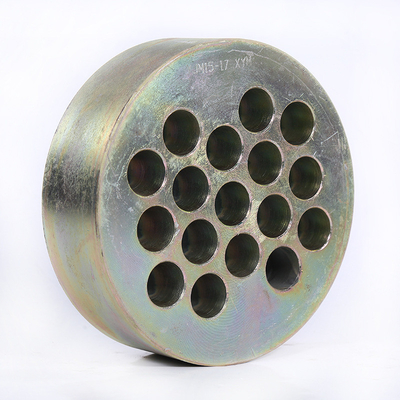
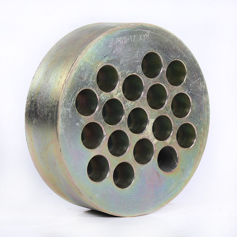
(1) Round Anchor
The specification model is denoted as YJM15-N (YM15-N) or YJM13-N (YM13-N); this sort of anchor has excellent self-anchoring performance. For tensioning, a through-center jack is commonly utilized.
(2) Flat anchor.
The specification model is expressed as: BJM15-N (BM15-N) or BJM13-N (BM13-N) (B, the first letter of the Chinese Pinyin for flat anchors, represents the meaning of flat anchors); flat anchors are primarily used for bridges. The horizontal prestressed surface, hollow slab, and low-height box girder ensure an even and appropriate stress distribution while also reducing the structure's thickness.
(3) Wrapped anchor.
(Fixed-end anchorage) The specification model is denoted as JYM15-N (YMP15-N) or JYM13-N (YMP13-N); it is appropriate for situations when the design stress at the end of the component is high or the end space is limited. It employs extrusion. The machine applies the squeezing sleeve to the stranded wire. It is pre-embedded in the concrete and assembled as needed. After the concrete has set to the specified strength, it is stretched.
![]()
(1) When cutting prestressed ribs, use a grinding wheel saw rather than arc cutting.
(2) When the steel strands are bundled, they should be straightened one at a time, bundled into bundles, and not disorderly. The extruded or embossed anchorage at the steel strand's fixed end must be pre-assembled with the bearing plate and spiral reinforcement.
(3) The equipment and instruments used for prestressing must be constantly maintained and calibrated.
(4) Before the prestressed tendons are tensioned, the concrete strength and compression test result must be submitted. When the compressive strength of concrete meets the design criteria and is not less than 75% of the design strength grade, prestressing can be used.
(5) Before tensioning the prestressing tendons, wipe the surface of the bearing plate and inspect the concrete behind it. Before tensioning, repair any cavities in the concrete with epoxy mortar.
(6) When the anchor is fitted, the anchor plate should be straight, the clip should be tightened, and the clip's position should be uniform; nevertheless, the clip should not be hammered too hard when tightening the clip to avoid damaging it.
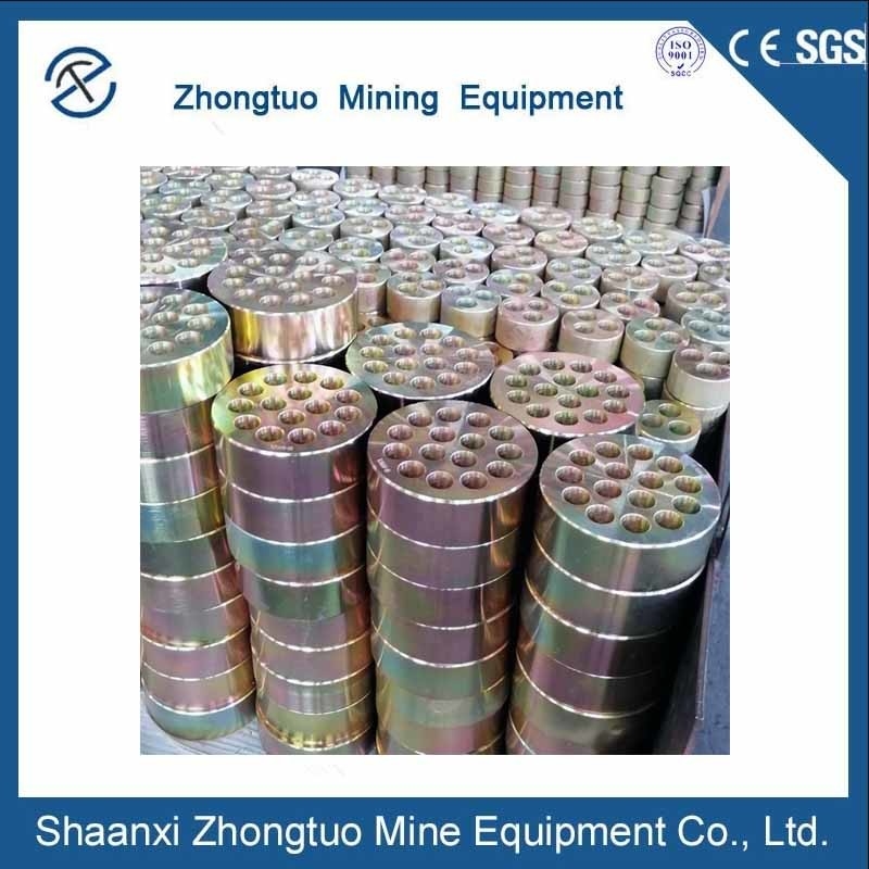
Our products are sold all over the world, you can rest assured.